|
|
 |
|
|
CHRISTCHURCH AND DISTRICT MODEL FLYING CLUB
BMFA affiliation no. 2581
|
|
|
|
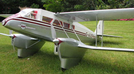
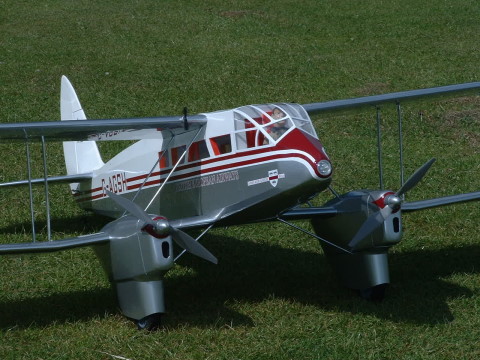
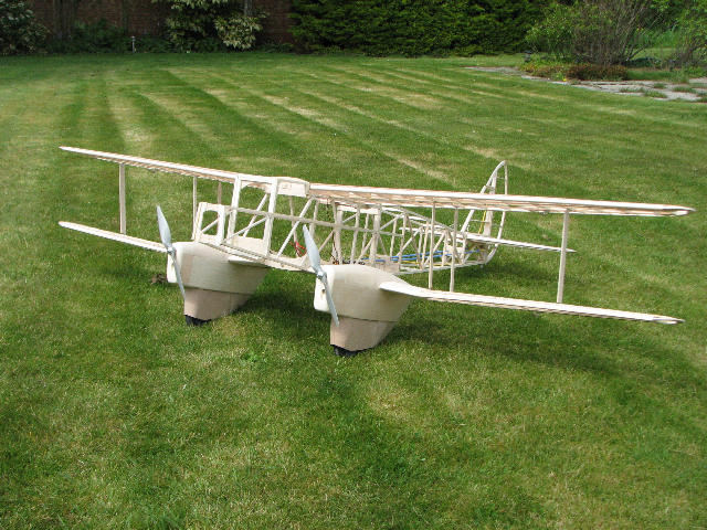
TREVOR HEWSONS DH 89 RAPIDE: a superscale Keil Kraft kit
|
|
|
|
The Rapide is another Ivan Pettigrew plan The specs, taken from Ivans website, are as follows:
D.H. Rapide. (DH 89) Scale 1/7.5. Span 76 ins. Wing area 1100 sq ins. Length 56 ins. Originally powered with two 27 turn Kyosho car motors, wired in series from 16 cells, driving 11 x 7 props through 2 1/2:1 ratio gearboxes. Thrust 50 oz static at 5,800 RPM on 18 amps. Weight 113 oz on wheels, 125 oz on floats. To save weight and achieve slower more realistic flight, it has been found better to use two Magnetic Mayhem motors in parallel from nine cells turning 11 x 7 APC-E props 6,000 RPM through 3:1 ratio gearboxes. Static thrust 52 oz on 32 amps, 16 amps to each motor. These are original plans that have not been upgraded, so the quality of the drawings is not up to that of later plans, but there is adequate detail for experienced builders. This model is capable of slow scale-like flight, but needs co-ordination of rudder and aileron. In slow speed gentle turns in a model like this, adverse aileron is sometimes necessary to keep the angle of bank from increasing. Mixing aileron and rudder is not the answer. Now read on!
|
|
|
|
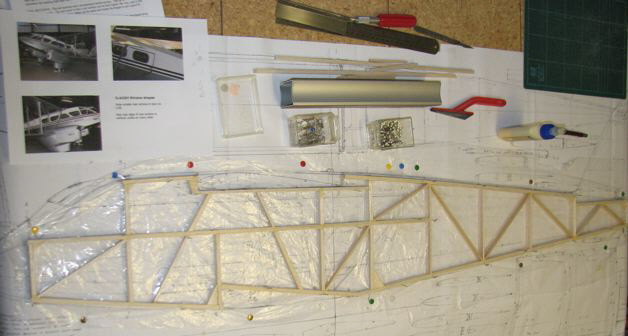
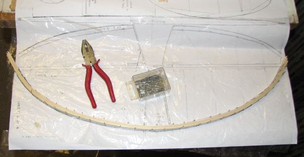
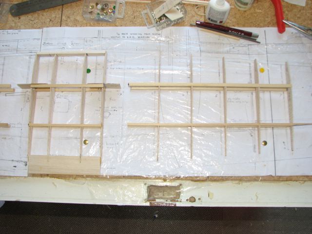
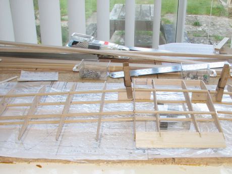
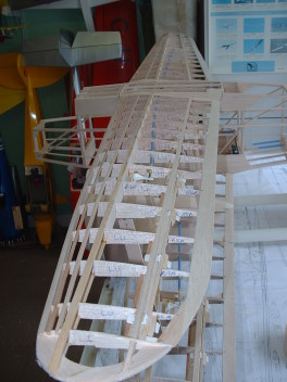
Wed 9 Jan 2008. Two side frames built on top of each other, as per 1960's tradition. Tomorrow we see if they will separate . . Out of interest these side frames used almost one 3in wide sheet of 1/4in balsa.
|
|
|
|
|
|
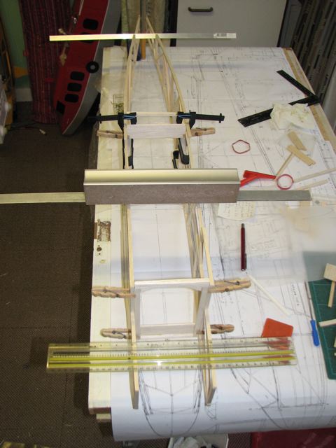
Fri 12 Jan. The picture shows just one former glued in place. If you think the number of clamps and alignment bars indicates a degree of paranoia on my part, I wouldn't argue. After all, it did take me several attempts yesterday just to fabricate the two simple formers you see here, which is why I left any attempt at installing them till this morning!
I feel that the nose should be pulled in whilst glueing in the second former, but the wing seat area will bulge if I do that. So really the cross pieces fore and aft of the wing seats should be fitted next to firm up the mid section. The only problem is, I can't find anything on the plan about these, so was hoping to tailor them to the wings - which haven't been built yet.
|
|
|
|
|
Trevors approach to modelling could not be more different from mine: just look how neat and tidy his workbench and modelling room are, compared with mine on the Catalina pictures! - Ed
|
|
|
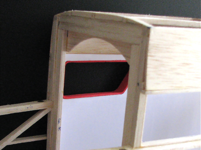
Andrew Tubb writes: I remember the SZD canopy hoops, the glazing of which is progressing well, were only 3 laminations thick, and as weak as water. I wish I'd had enough thought to add a strip of 1/32" ply, to give a little more strength, considering the handling it's had to take.
Impressive none the less and...more rewarding by laminations, and can be just as strong (and far easier to razor plane to the correct section than the spliced sheet method - Ed)
Back to top
|
|
|
|
|
|
|
25 Jan 08 Whilst I don't think that almost building a set of tail surfaces in two weeks really qualifies as express building, it is always good to know that others realise how much work is involved in such modest progress.
|
|
|
|
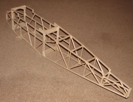
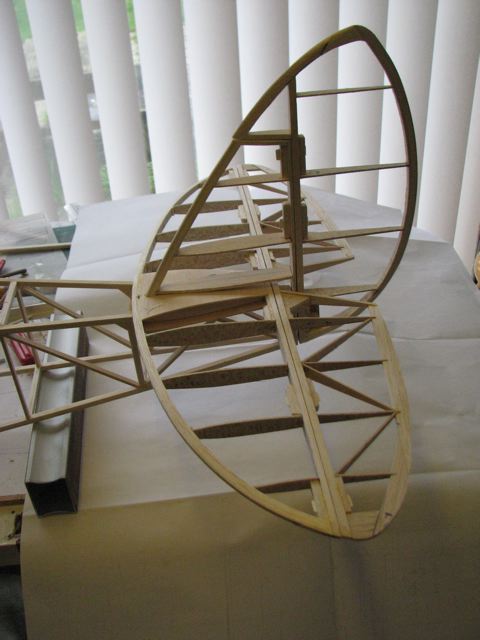
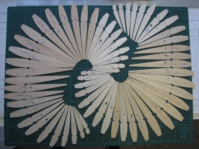
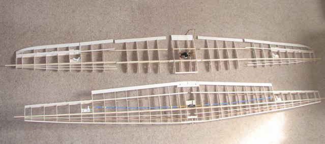
31 Jan 08 - Guess whos bored with ribs! Next time I will choose a subject with straight wings (and preferably only one!)
|
|
|
|
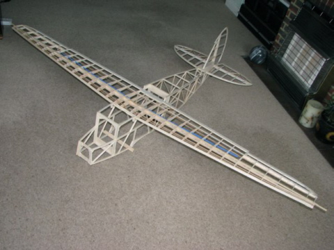
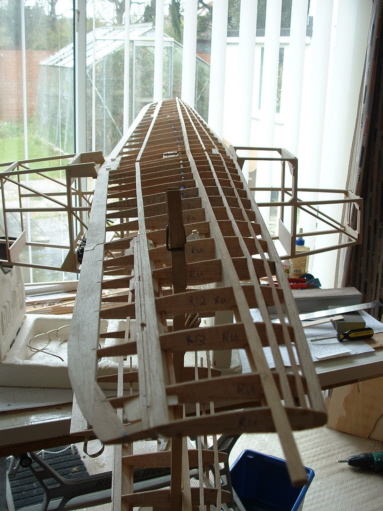
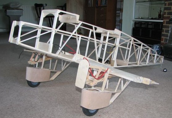
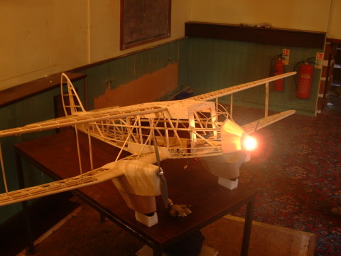
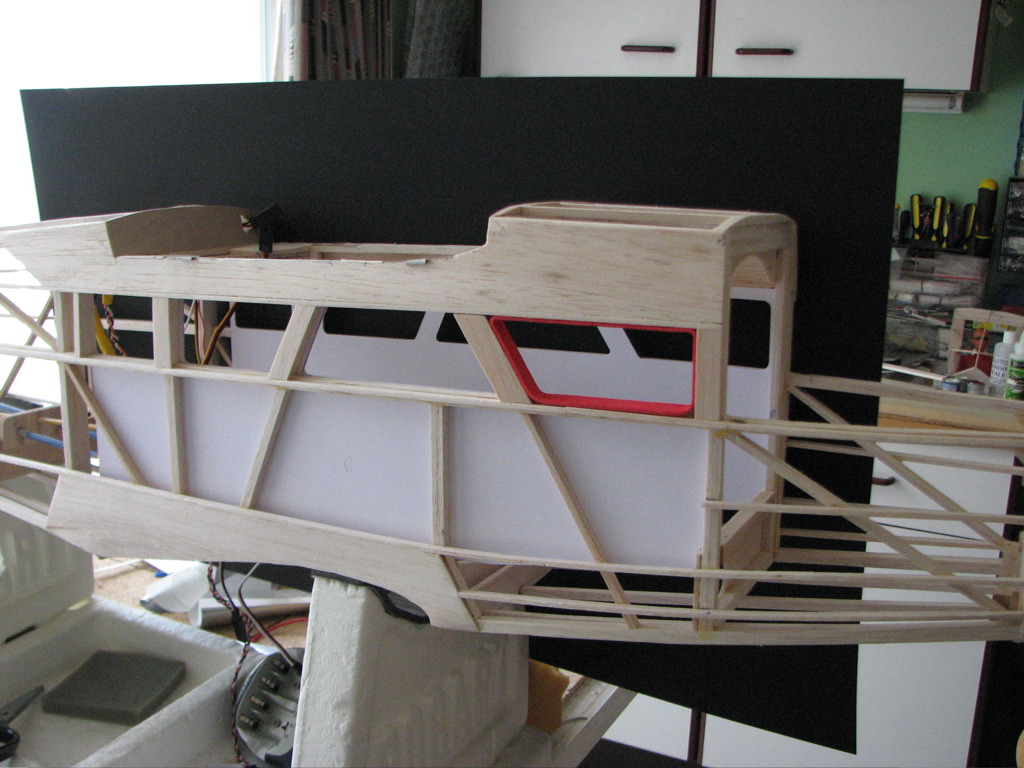
I thought I might be more motivated to spend time in the model room if it was tidied up a bit, so took the opportunity to take a picture whilst the model was moved out of vacuum cleaner range. Ivan did say that the Rapide was one of his earlier designs and that he had evolved better and easier ways of doing wings in his later models. I am beginning to appreciate what he means - there is a lot of work in this structure, and the prize for finishing it is that I get to do it all again with the added complications of four dihedral breaks, engine nacelles, undercarriage and, if I'm feeling
masochistic, flaps. Meanwhile, it's back to the bellcranks and servo installation. .
|
|
|
|
Ken Spokes says: Trevor, Looking very good. I always think it is a pity to cover these built-up airframes - they have a magic of their own. Been putting a new felt roof on the Summerhouse for the last couple of days - bashing in tacks made a nice change from all the fiddley bits I seem to be making these days for the L4.
|
|
|
|
|
|
|
The electronic side of building has been exercising Trevor lately, and he started off a round of correspondence about motors and battery size (with a diversion into landing lights) thus:
Having got started on the inboard sections of the lower wing, and with the prospect of engine nacelles looming, I thought it time to make a decision about some motors. BRC Hobbies have what looks like a good deal on the HiModel 2217-8T with a cheapo 20A ESC for £26.99, see:
http://www.brchobbies.co.uk/?page=shop&action=additem&item=334. In order to be able to use the ESC BECs, I am leaning towards 3-cell
operation, and just need to persuade myself that this is sensible. I have had this conversation before with at least some of you but, basically, comparison with the Sealand says that it should be fine, whereas comparison with my only other biplane, the somewhat smaller Stearman, says that anything less than 4 cells is a bit hopeful.
Vital statistics for the Rapide are as follows:
Span 76ins
Wing area (gross) 1100 sq ins
Wing area (nett - applying Ivan's 80% biplane factor) 880 sq ins
Likely weight 6lb
The BRC motors are rated at 200w. However, their working current range is given as 5 - 16A, and 16A on a 3 cell pack is more like 160w. Even
so, 2 x 160w would get me over the magic 50w/lb mark which, for a non- aerobatic cruising model ought to be enough - except that it is a biplane. . .
Last issue is prop selection. I haven't found a clear recommendation for the 2217-8T. However the 2217-7T and 2217-9T appear on the RCMDirect spec page with recommended props of 10 x 5 and 11 x 7 respectively, for 3 cell operation, so I am hoping that an 11x 5 might go well on the 8 turn motor.
Any comments or suggestions before I take the plunge and place the order?
Trevor
Clive was the first to reply:
Hi Trevor,
Regarding the power fo your Rapide I have serious doubts if 50 Watt/Lbs is viable for a draggy biplane. Experience with the Pup & Strutter would suggest 75 Watts/Lbs to be nearer the requirement & its better to have a little more power that not enough. With the Rapide weighing 6 Lbs I think you would require about 450 Watts & using a 3 cell Li-Po @ 11.1 Volts = 40.5 Amps, 45 Amps @ 10 Volts under load. Too high. I put your figures into MotorCalc & it more or less confirmed my thoughts with an average motor current of 47 Amps. I think you would be better off using a 4 Cell battery to reduce the current draw & using a motor/prop combination to give a max of 30 Amps x 14.8 Volts = 444 Watts. The battery would only add about 3 Ozs to the overall weight, nothing the you already low wing loading. That's my thoughts for what they are worth, you may see it differently?
Regards Clive.
Dear Trevor, I added,
Judging by the spare perfomance in the Sealand, I can't see why you would need any more power. But then I'm a carpenter not an electrician!
Trevor replied to us saying that Clive had expressed his (Trevors) worries perfectly :The motors I am contemplating will apparently take 4 cells but the ESCs bundled in with them won't. The other problem is that on 4 cells I couldn't use ESC BECs, so would need a receiver battery and/or uBEC.
Since writing my last e-mail, I spotted a bit more information on Ivan's plan: He initially flew his prototype Rapide at a weight of 108oz on 14 cells, driving two geared car motors in series, drawing 19amps. He later changed to two 27 turn car motors (again geared) running in parallel off a 9 cell RC1700 pack with a combined current draw of 24 amps, reducing the weight to 97oz. I make this around 250watts or barely 40w/lb.
I reckon my 3700mah 3 cell LiPo pack will give a bit more voltage than Ivan's 9 cell NiCd and, if I prop for a total current draw or around 30amps rather than his 24, on this basis I should have power in hand.
The Rapide is reckoned to be one of the most efficient biplanes ever built, due to its streamlining and wide separation of the wings. Could it be that Ivan's design has preserved something of this characteristic of the full size, causing us to be misled by comparison with Stearmans, Pups and Strutters?
Trevor
Once again I added a non-scientific wet finger:
As a layman, I agree with Trevor's analysis: all Ivan's planes seem to be "underpowered" at first sight, but we all know the benefits of twins, in that they do not directly compare with single-motor models. Go for the 3 cells Trevor! Trust Geoffrey de Havilland to work his majic!
Mike
Trevor came back to us with some more thoughts: In spite of all my deliberations, I think I may have got it wrong! The document from the RCM site was the basis for my saying in an earlier e-mail that " I haven't found a clear recommendation for the 2217-8T. However the 2217-7T and 2217-9T appear on the RCMDirect spec page with recommended props of 10 x 5 and 11 x 7 respectively, for 3 cell operation, so I am hoping that an 11x 5 might go well on the 8 turn motor." Imagine my surprise then when the 2217-8T motors arrived this morning from BRC, complete with a data sheet which recommends an APC-E 8 x 6 as the ideal setup for 3 cell operation! I am now wondering whether this motor is a subtly different configuration from the 7 and 9 turn versions specified on the RCM site, the latter being a high torque variant. However the Kv of my 8 turn motor is quoted as 1100rpm/volt which still sits between the 1400 and 1050 quoted for the 7 and 9 turn versions from RCM so I don't understand why it appears to be so much 'hotter'.
Scale prop size for the Rapide would be a bit over 10ins, so if I can get away with a 9in one it may still look reasonable. I will try to do a test of my own over the weekend.
Trevor
aka Confused of Barton
and finally....
Okay, I just dashed out in a gap in the rain to run up one of the HiModel 2217- 8 motors. I pinched the APC 9 x 6 prop off the Lazy Bee and recorded 8,500rpm at 15.2 amps off a 3s 3700mah battery that hasn't been charged for a couple of months. The ESC was still set at its default 'soft' timing, although it ought to be changed to 'hard' for use with outrunners.
This 15.2A with a 9 x 6 compares with BRC's data sheet giving 14.5A on an 8 x 6 APC E as their ideal set up and an alternative of a 9 x 4.5 APC E drawing 17.8A. This suggests that my less than fresh battery and/or the soft timing may be keeping the current draw down a bit. Even so, my thrust calculator claims that 8500rpm on a 9 x 6 equates to around 27oz of thrust, so two of these should give over 3lb of thrust, getting the thrust/weight ratio over the 50% mark which is in the right ballpark. Pitch speed is more than enough too so, if the current does go up too much with the combination of hard timing and a fresher battery, dropping back to the 9 x 4.5 props should fix it.
I confess I did find myself wondering how I might re-deploy these motors and realised that they would transform my P38. It currently draws a measly 20 amps of a 2s pack so switching to 2 x 15amps off a 3s pack would more than double its power! Unfortunately, the tired old airframe probably wouldn't stand the strain so I might to better to build something else - I've always fancied a Tigercat - 60in span, with retracts, perhaps?
However, I will probably fit these motors to the Rapide at least initially and see whether I am unhappy with the visual impact of the small props or with the overall power level before looking at any alternatives. At least it is good to know that replacements of a very similar form factor seem to be readily available.
Back to the wing ribs, then. . . .
Trevor
Now for more esoteric fare: Hello All,
Thanks for the input on the motor selection. I will try the three cell route for simplicity. Of course, I may end up with lead in the nose.
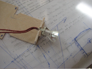
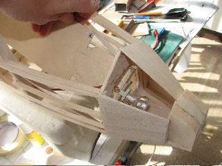
Talking of the nose, another challenge to be faced later is the question of the landing light. This needs to be about 1.5ins in diameter, with a convex lens. I seem to remember that, before the style gurus got at such humble domestic items, some torches (or flashlights as we always used to call them) had a suitable shape. I am thinking of operating the light through a little ESC so can be flexible on bulb / LED voltage, although Clive will no doubt be quick to point out that if I want to get full brightness out of a 12v car headlamp bulb I will need to go to 4 cells!
Hi Trevor, replied Ken Spokes,
I think you will be lucky to find a torch lens in this day and age to meet your requirements. I would be inclined to form one by heating plastic or acetate sheet and pulling it over a spinner of the right shape. I would use a piece of ply with a hole cut in it to force the sheet over the spinner. You will probably require three pairs of hands for the job. I am sure with a bit of trial and error you will end up with what you want. You could form the reflector the same way painted silver on the reverse side.I might have what you want in my spinner box.
Cheers Ken
...and from me: I think you are more likely to find a good reflector in an off-the-shelf torch (and better reflectivity than painting a moulding silver) but as Ken says, the "lens" might have to be handmade. One of the high-intensity zenon(??) (I meant Halogen, I think) bulbs would be really good.
Andrew also had input:
I keep being drawn to the idea of a wide angle large LED, and you can get ones that work on 5-6.8v, or similar, which would allow on/off at the receiver effectively
|
|
|
|
|
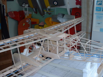
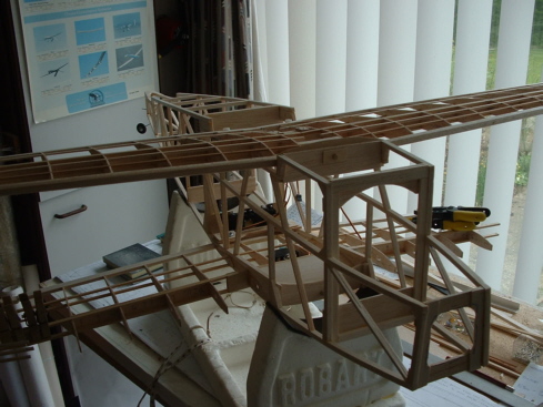
It seems to have taken an age, but the major components of the lower wing are more or less built. Next step is to join the three inner panels and fit them to the fuselage. I was going to build the nacelles onto the inner panels first but, because of the anhedral, I feel I need to have the inner panels joined in order to provide some sort of vertical reference as I build the nacelles onto the wings.
|
|
|
|
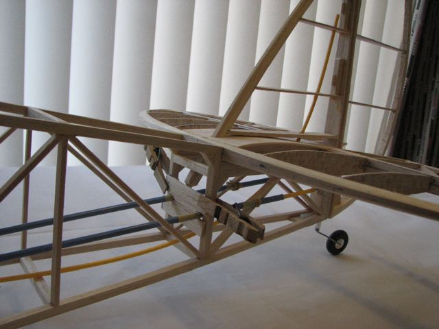
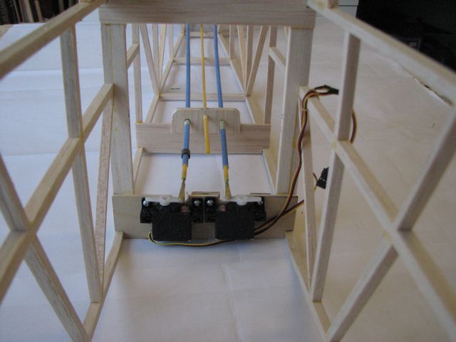
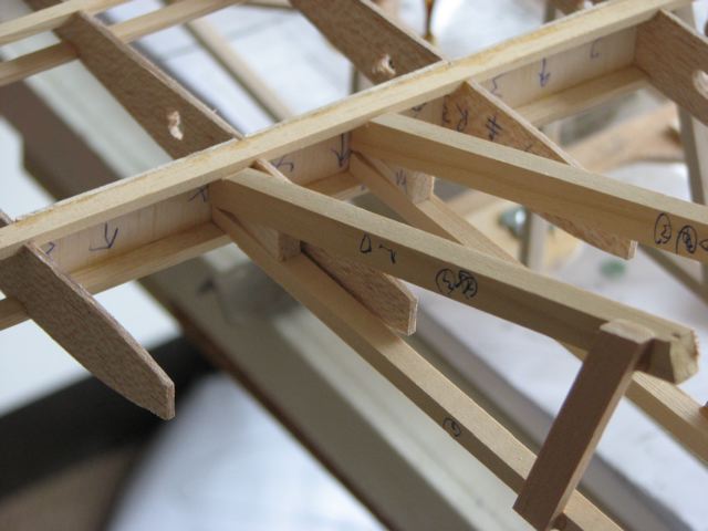
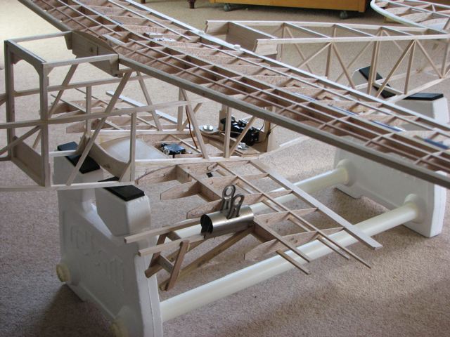
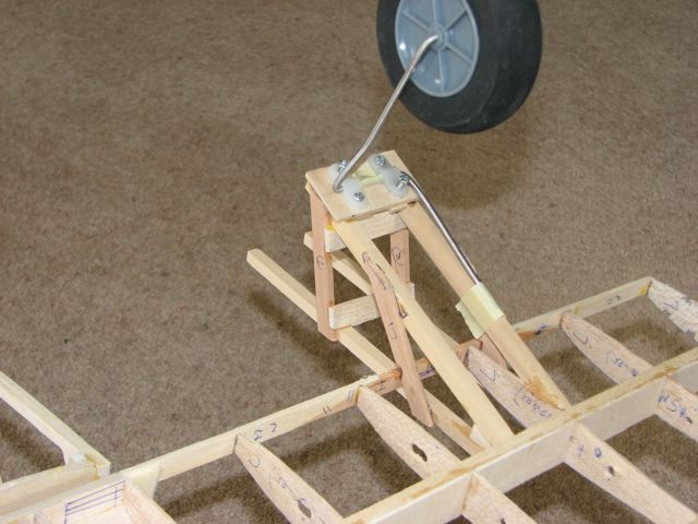
24 March 08. I have begun dry fitting the nacelle framework to the lower wing. The two attached pictures (with the model inverted) show how the main members meet the mainspar. The second picture also shows how far forward the nacelles extend - the u/c attachment point is at base of the vertical strut. I say vertical, it isn't of course. In fact, what with the anhedral on the wing panels and the sweep on the leading edge, it's very difficult to see how to line anything up or to get any glueing area into the joints.
|
|
|
|
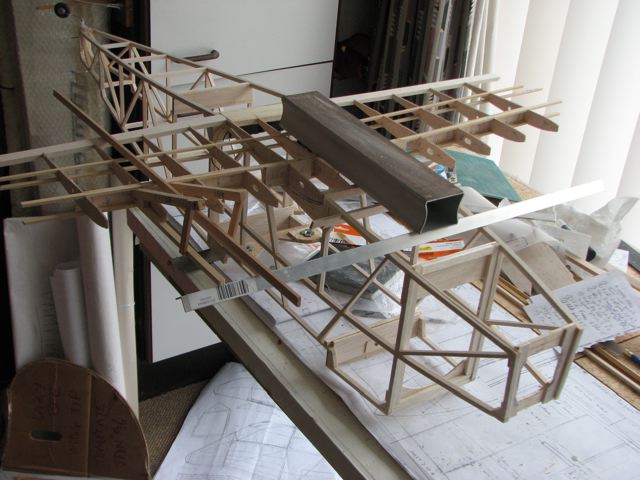
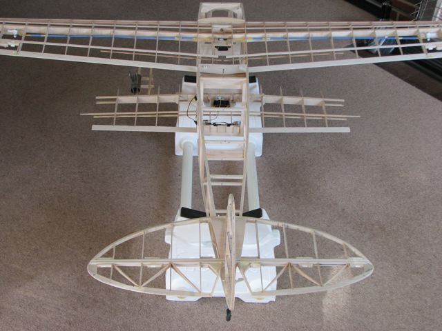
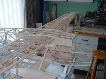
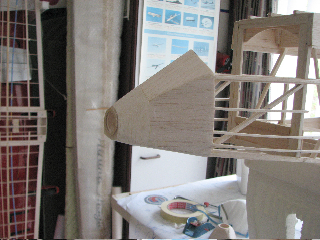
These two pictures clearly show the divergence between the upper and lower wings. Apparently the wide separation of the two wings was a major contributor to the Rapide's efficiency compared to other biplanes. Good news is the wings almost line up. Bad news is that, even at this stage, it is clear that the model is going to be tail heavy. Time to reconsider the 3 vs 4 cell debate and motor choice!? I bought a couple of MR11 halogen lamps at B&Q today. 26deg beam width, 35mm diameter, 35W at 12v. Once I have worked out how to connect to them, I will see how much current they draw off a 3s pack and how bright they are.
There is still a bit more to do on the wing attachment points but I don't think I can put off the job of attaching those nacelle frameworks much longer!
|
|
|
|
The November 2003 copy of Flying Scale Models has a whole section on the DH89, accompanying Chris Golds 60 plan and article. I took it round to Trevor, with a health warning: dont get unsettled when reading this. The problem is that Ivans plan of the Rapide is one of his earlier efforts and does not seem terribly well thought-out (sorry Ivan!): for instance; the nacelles dont fit between a set of ribs, and cannot be located correctly once the LE is in position; the wing seating is an awkward compromise over scale fidelity; the wing structure is over-complicated, but also under-engineered. Im glad Im not building it! But Trevor has made such an excellent job of the model so far and it really is going to look marvellous in the air. And he is planning on having a landing light in the nose!
|
|
|
|
|
|
|
|
|
|
|
|
|
 |
|
|
|
 |
|
|
|
 |
|
|
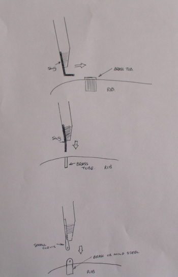
The struts should be mainly for appearance, in that the main spars are strong enough to take the bending loads. I am a bit uncertain about torsional rigidity though, since there is no D box other than on the inboard sections of the lower wing. I am hoping that the covering will stiffen things up enough, since it is a slow flying model. If not, I just might have to add incidence wires. Having opted for one-piece wings top and bottom, I can't leave upper and lower pairs pre-rigged together, so I am looking for a strut attachment method that is not too much trouble in the field - preferably one which doesn't give me the opportunity to drop screws in the grass!
|
|
|
|
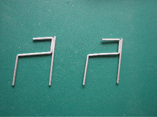
Ken Spokes sent this sketch Attached are three possible methods I have used for fixing struts. They have all worked well for me. Hope you find this useful."
Andy Tubb: if it was me, I would 'Z' bend on top and put a piano wire spring loaded 90deg bent wire in the bottom end. You can then use a length of fuel tubing to 'belt and braces' the whole thing, slipped up/down over the end to the wing surface. If the wire cross bracing is for strength, then doing in place may be best to get correct position, 'shape', etc, but if it is for appearance, then why not, after running the wire through a piece of thinners soaked scotchbrite, kevlar thread and tie the cross-over and cyano. Then paint with silver, or what ever colour choice is required. The joint may eventually slip, but a smidge of runny cyano will have that fixed, again. You could substitute the kevlar with very thin strand copper wire. I have some already stripped and twisted as a 3, which is still less than 1mm diameter. You could use some of the thin copper coloured stuf inside your t.v aerial lead. That stuff is almost as thin as hair, (if you're a horse).
|
|
|
|
|
|
Isnt language a strange thing? Here we have the wheel trousers taking shape (called wheel pants in the USA). I suppose its a perfectly logical description but it just seems so bizarre. Perhaps there was no-one in the industry who was in charge of designations management when they first appeared? - Ed.
A few days later, I was wishing I hadnt said that! Trevor said he thought that wheel pants were what we would call Spats (ie a fairing streamling the actual wheel itself, not the equivalent of Trousers (a fairing over the undercarriage). So I asked Luke Z, a well-known modeller from Kansas and he said:
Mike,
That is a very interesting question. I am not expert and popular usage of a term does not mean that the popular usage is correct. But your friend is right, if you were to say "wheel pants" in the US, people would believe that you refer to the fairings that go around the actual wheels, not the undercarriage struts. In other words, what you call Spats we call Pants. Only we never really say just pants, it's always "wheel pants." And again, just because this is what everyone calls them, does not necessarily mean it is correct usage. Be that as it may, no one in the US would think wheel pants refers to the undercarriage fairings.
So then, what word do we have for your Trousers? None that I know of. We would just call the undercarriage the undercarriage. If they have large fairings on them we'd just say they have fairings. I don't know of a special word for it.
You may want to ask a few more Yanks what they think, and I'd be interested to know if anyone disagrees with me...
I suppose I should stick to modelling and leave language to the experts. Just dont ask what Scratch Building means....Ed
|
|
|
|
 |
|
|
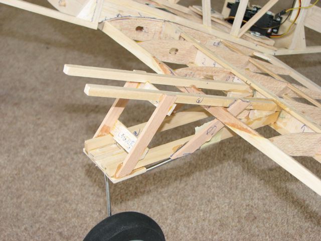
The trousers are retained by two screws into the nacelle floor, accessible (just!) through the wheel aperture. I have got the firewalls drilled out and fitted now and hope to start sheeting in the nacelles today - until I run out of 1/16 balsa again!
|
|
|
|
|
|
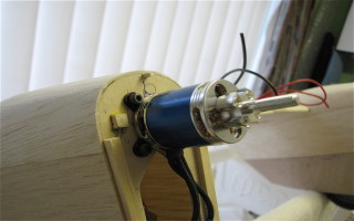
Having got the firewalls prepared, the u/c in place and the nacelles partly sheeted, I temporarily mounted the motors - and immediately convinced myself that 9in props just didn't look right, so the motor search began again.
After the usual dithering I ordered two KD2217-20T motors, which arrived this morning. Youll find the specs and cost at http://www.giantcod.co.uk/product_info.php?products_id=402409&osCsid=74be1b249a36537075abf10e9154cbaa (Giant Cod RC: it is really real, apparently - Ed
Borrowing a 10 x 7 APC E prop off the Sealand, I recorded 15.2A for 7,700rpm off a 3s 3700mah LiPo - Perfect! The motors use the same size cross mount as the HiModel ones so fit the captive 3mm nuts which are already fitted to the firewall. There is a minor difference in the positioning of the prop backplate but, since I haven't started on the cowls yet, that is no problem. ...and is the motors performance all that different from the ones in the Sealand? Pretty well identical, but at £10 per motor as opposed to £30 apiece for the Hyperions - and no need to press motor shafts through either. I did initially contemplate taking the Hyperions out of the Sealand for the Rapide and replacing them with something less powerful. However, since I have taken to flying the Sealand off grass without the wheels, the extra power is now needed, if only for the first two or three seconds of each flight.
Came back from Howard's today via Channel 4 and re-stocked on 1/16th sheet. I hadn't done the motor test by then though, so I still need a couple of 10 x 7 APC E's.
These 3700 LiPos continue to amaze me. Today I did two flights with the Sealand (with the same battery), total duration 16 minutes. Re- charging put only 1.5ah into the battery. The Chorus Gull had a 7 minute flight (this with the changed gear ratio, so I landed early to check that nothing was overheating). This 4s pack took just 1.35ah to recharge. 30c LiPos? - bah, who needs them!?
|
|
|
|
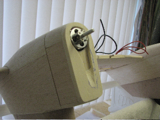
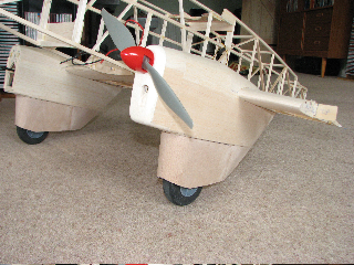
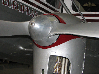
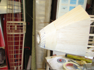
24 April. I am struggling to find suitable spinners for the Rapide. The ones on the Sealand are Robotbirds Aerospinners, 32mm diameter. It was one of these that I borrowed for the picture above, but it bears no relation to the real thing, on the right.
I am prepared to compromise on shape - after all, my cowl shapes are by no means faithful to the full size. However I would like to find something of the right size - anywhere between 32mm and 38mm would be an improvement (I suspect though that these are still the old 1.25in and 1.5in sizes, so maybe I need to find a genuine metric spinner?) . The major constraint though is the prop drivers (a picture above this one). These are bolted to the motor and I am reluctant to abandon them and resort to moving the shafts around, which would almost certainly re-position the prop and necessitate significant cowl re-work.
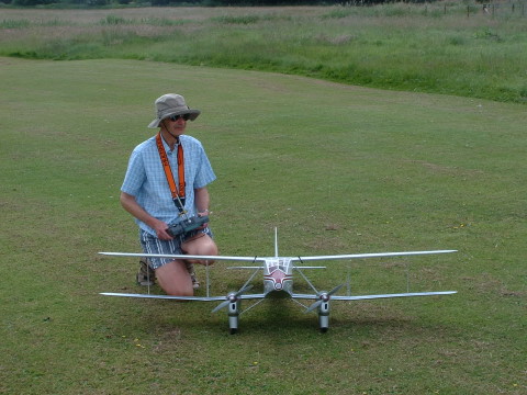
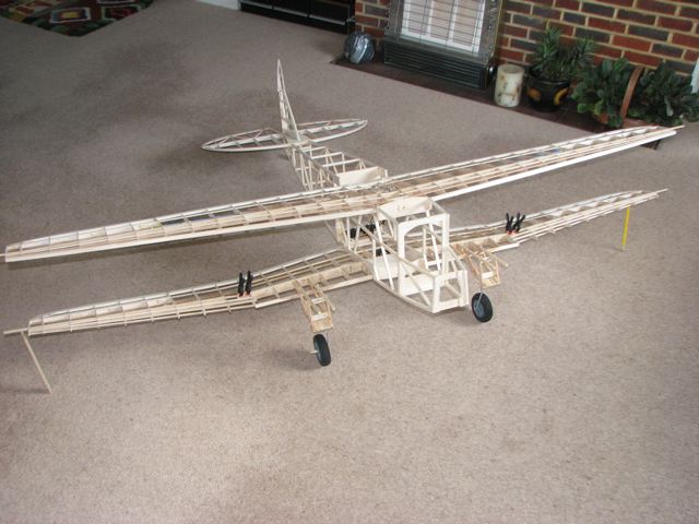
And below is the proof that Trevor ciuts the grass as well as balsa wood (or was it Mary who did the grass?) The model weighs 3lb at this stage - Ed.
|
|
|
|
|
|
 |
|
|
|
30 April 2008. Snap Inspection Day. Its an awesomely difficult build, this one, and you only realise how complex it is when you see the structure close up. Not for beginners! - Ed
|
|
|
|
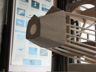
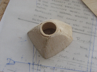
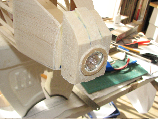
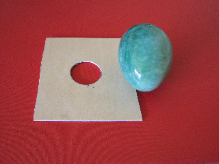
Carving of the MkII noseblock went better, but the shape didn't look right, so it was marked-up for surgery! Before finally shaping the block, I felt I needed the lens in place. One of Mary's decorative Agate eggs proved to be a perfect mould!
|
|
|
|
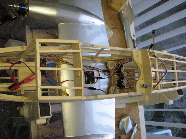
17 May. Rather than face up to the challenges of the cockpit and cabin interiors and associated glazing, I have made a start on the covering. Herewith a picture of the upper wing, with a bit of gratuitous extra drag added in the form of generators. I fitted both wings and the struts before shrinking the Profilm taut, just to make sure that the wings stayed in alignment. Seems okay so far, and the covering has added quite a bit of torsional stiffness.Lower wing is well underway now. I think I will then fit the motors, speed controllers and wiring next - just to put off tackling that cockpit for a bit longer!...and later: After a solid week slaving over a hot covering iron, both wings are now covered. As you can see below, I haven't quite got the wiring sorted out yet!
I was grinding through the tedious job of profilming the twelve struts, when the covering iron decided it had had enough and gave up the ghost. However, the wiring is more or less sorted so I might use the enforced covering interlude to do run the motors up. It's either that or face up to starting on the interior!
|
|
|
|
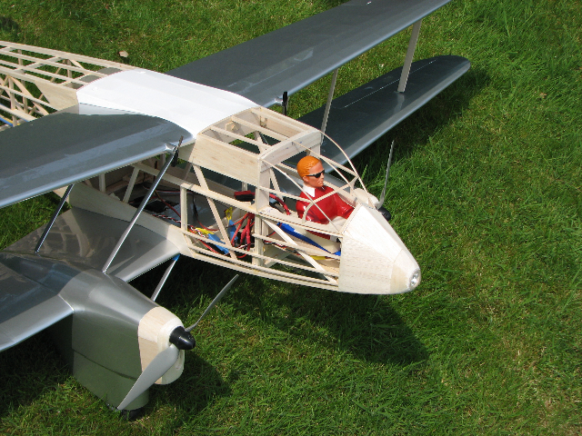
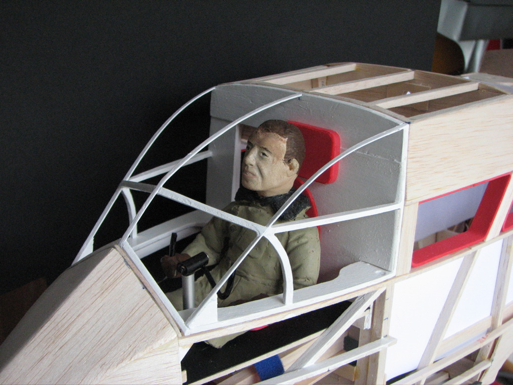
The saga of the pilot: are you sitting comfortably? Trevor bought a shop pilot who was really a bit too big and certainly far too garish. A colleague found an old 1/8th Petes Pilot in his spares box. This fella used to be a DH2 driver in his youth, seeing off the Fokkers, but has been sitting forgotten for about 8 years. He did have goggles and a flying helmet, but this was thought inapproriate for a civilian in a closed cockpit, so a spare head was substituted, giving Trevor this rather serious-looking chap, still in his Sidcot flying suit. He looks a bit like the walking guide author A Wainwright, doesnt he?
|
|
|
|
|
|
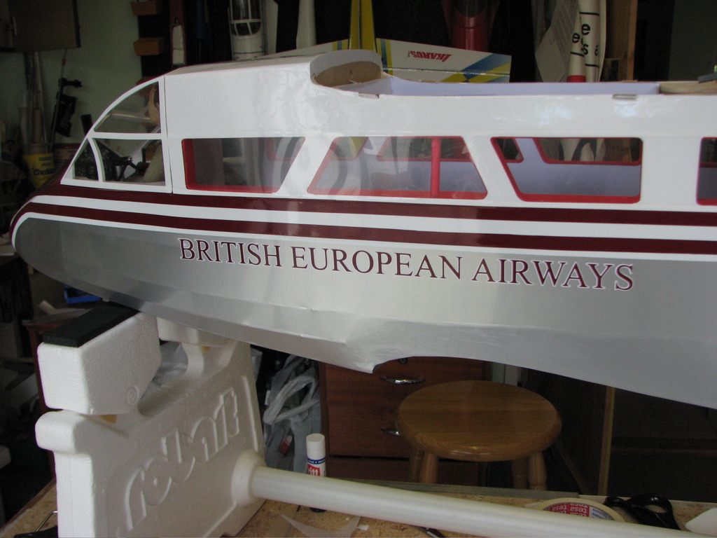
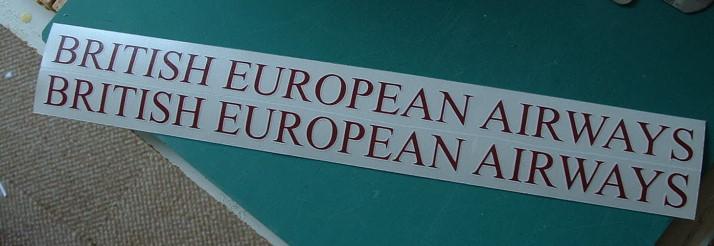
The lettering done by Lush Signs looks very promising. I have applied one set of registration letters and they went on very easily. The letters have been cut out individually but remain on their backing sheet and are supplied with a layer of application film over the top. This film is sufficiently tacky to lift the letters from the backing paper. One end is positioned on the model and the sheet is then rolled down, placing each letter in its correct position. After gently rubbing the letters down, the application film is peeled off and the job is done.
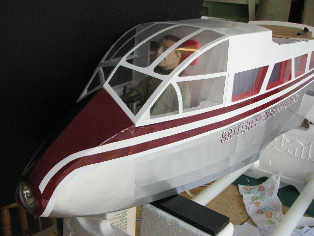
The British European Airways lettering has also been supplied on a backing sheet, with the burgundy letters superimposed on the white creating a nice even white margin. Again there is application film over the whole lot so I am hoping that these will go on equally easily. They confirmed that they are perfectly happy to do these small jobs so, if all goes well, I will do a short piece for Sloping Off.
Got the fin covered after lunch, but its a bit hot in my model room now. That's what comes of letting these Winter projects overrun!
|
|
|
|
|
The BEA lettering has been particularly successful, with the burgundy letter and white outline faithfully reproduced.
|
|
|
|
|
|
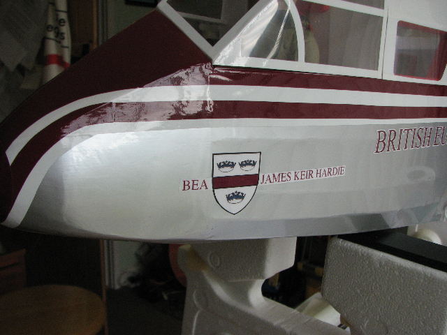
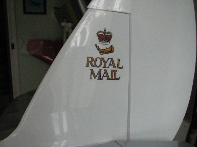
Two more pics showing nose and tail art, both taken from photos of the full size. They are printed onto decal sheet but, when I tried to float them on, the only thing that floated was the ink! Some basic weather protection would seem to be in order so I now have some fuel proofer drying on a couple of samples. Looks good so far, but it could yet all go wrong!
|
|
|
|
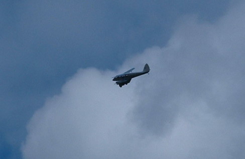
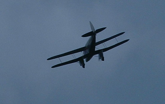
15 June 2008. The maiden flight passed off without a hitch and was seen by a select group at Howards Field. The motors were a bit noisy, but this may be due to the little generator props chattering on their shafts. The model looks a treat in the air and on the ground. Just the interior to finish!
|
|
|
|
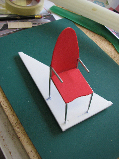
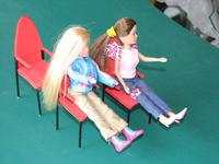
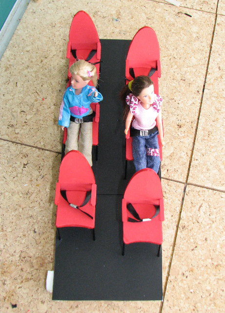
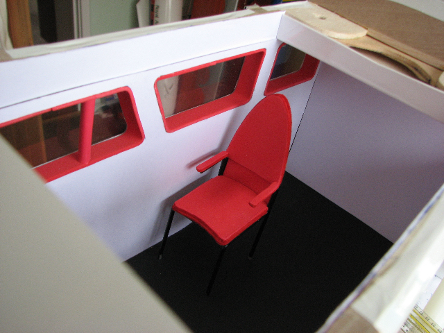
The trouble with starting interior decorating is that it never gets finished! Trevor has begun making seats to fill the cabin.
|
|