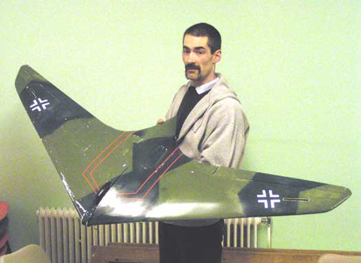

I'll try not to put too much glibness into this as I tend to lose the plot. So "Just the facts, Ma'am, I want the facts!" The plan was published in the May 1998 edition of Electric Flight International, ref. 2668. It is designed by Chris Golds.
After setting out the pins to the rib outlines for as many as the building board would allow and having suitably protected the plan from glue run and with enough strip wood prepared, bend, cut and glue the ribs. These can be made quite quickly, being glued with gap (medium) superglue.
The front and rear spars need more effort and time, because of the 1/64" ply doubler on the front spar and having to splice/scarf join them just inside the outer limit of the doubler. Some care is needed with the hole for the fan as later positioning and fixing is affected by the relative position in the intake/eflux "gulley". Anyhow, the fuselage, such as it is, is basically just there to hold the flight battery but in retrospect, some more attention to strengthen in the "nose" between the leading edge roots would have been good - or maybe not having the model impact the ground would have helped!
A lot of mild cursing and head scratching was involved in getting the ribs in the right places on the spars as the depth of spar close to the root is more than the corresponding hole in the rib at each rib position. After the ribs were basically glued, there now comes the cutting and fitting of the cross bracings between each rib. Information for these seemed to be less than adequate but the lateral thought applied seemed to pay off as, after two brief slope flights the bracing was still intact, even if one of the leading edges wasn't, after a shortened second flight.
One of the harder parts of construction was getting the drag rudders to work. A visit to a local fastener supply warehouse provided M2 screws, nuts and washers and a box of 1000 small hatch cover screws which never seem to get less until suddenly you've got none left. (need some!?) So, enjoy making the drag rudders. I did, but springing them to close was a pain. Coiled springs proved to be either too weak or too strong, elastic bands would wear out and there was no access to replace them. In the end 0.6mm welding wire proved thin enough and strong enough to close the rudders, whilst allowing the servo to open them.
I wanted the elevons to be operated with as low a profile horn as possible. As there is nearly an inch of depth at the elevon inner leading edge, it was possible, with top hingeing, to fit the servo in the wing and have the pushrod exit via a hole in the wing trailing edge and fit the horn to the elevon leading edge matching this hole.
Covering was Profilm, although if I'd taken one member's advice, I could have sheeted in 1/32" balsa and then used light paper or tissue. Painting would then have been easier. Acrylic paint sticks to suitably keyed Profilm, as long as it is not disturbed afterwards. A better bet was to use an aerosol called 'primer for plastic' which seems to provide an etch that stays very slightly tacky and makes an excellent key for acrylic paint.
The ducts for the two Wemotec midi fans are as per construction instructions, but efficiency of this won't be proven until some repairs are made and a suitable bungee launch device constructed.
Thanks to all for the advice and encouragement, and to Brian
for taking on the challenge of sloping the Horton on its first
flights.