SLOPING OFF...
...the Newsletter of Christchurch and District Model Flying Club for...December 2025
SUPER SCOOPER REVISITED
by Mike Roach
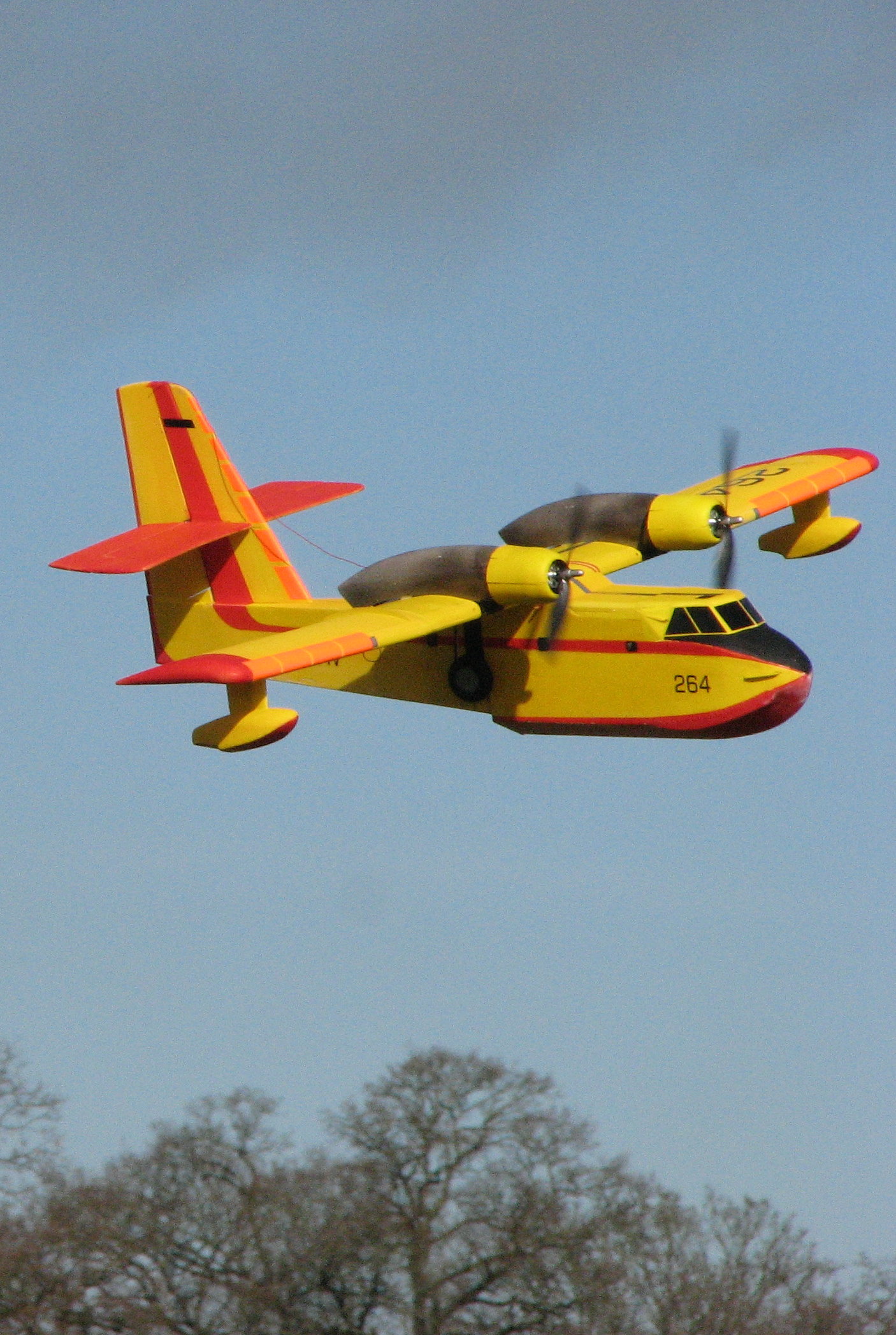
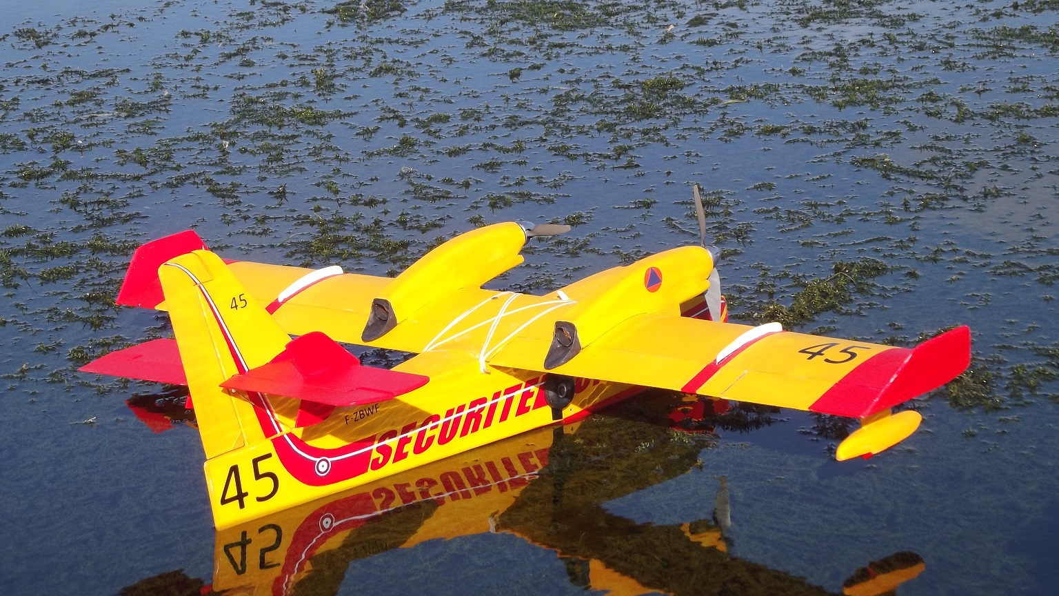
Seventeen years ago I started construction of my first attempt at a “Spirit of Ivan” model, a 72” span version of the Bombardier CL415, the gas turbine powered “Super Scooper” that is featured in almost any news about forest fires. The big yellow water-bomber swoops over the fire and releases tons of water, having skimmed over a local lake or the open sea to pick it up and carry it where it was needed. It’s big, tough, square and nowadays, very well documented. It was a perfect choice for a relatively simple lightweight electric powered model to fly off our Club’s newly acquired lake at Longham and perhaps foolishly on Christchurch Harbour, using my Club’s safety boat as an aircraft carrier
The 3-view I used came from an RC Groups contributor, “Rotorheid” who built a depron version. A subsequent much more accurate one became available a few years later on the Seawings website and this is the one I used for my revisions to the plan and which sparked this second build.
The completed model flew very well both off water and grass. I sent my plans to RC Model World and it was published as a plan and short kit in 2009 and these are still available from Sarik Hobbies. Eventually the model crashed beyond repair due the flight battery deciding it had a better view out if it moved back a foot or so, but the look of the model in the air spurred me to try again. I built a 48” span depron CL215, with the big round engines and none of the aerodynamic aids placed on the turbine version
and then a couple of the 415 also in depron at the same scale. They are such fun to fly and so easy to build. The plan for the 415 is available on my Free Plans pages at RC Groups and a 215 is a very simple conversion if you prefer the piston engined version.
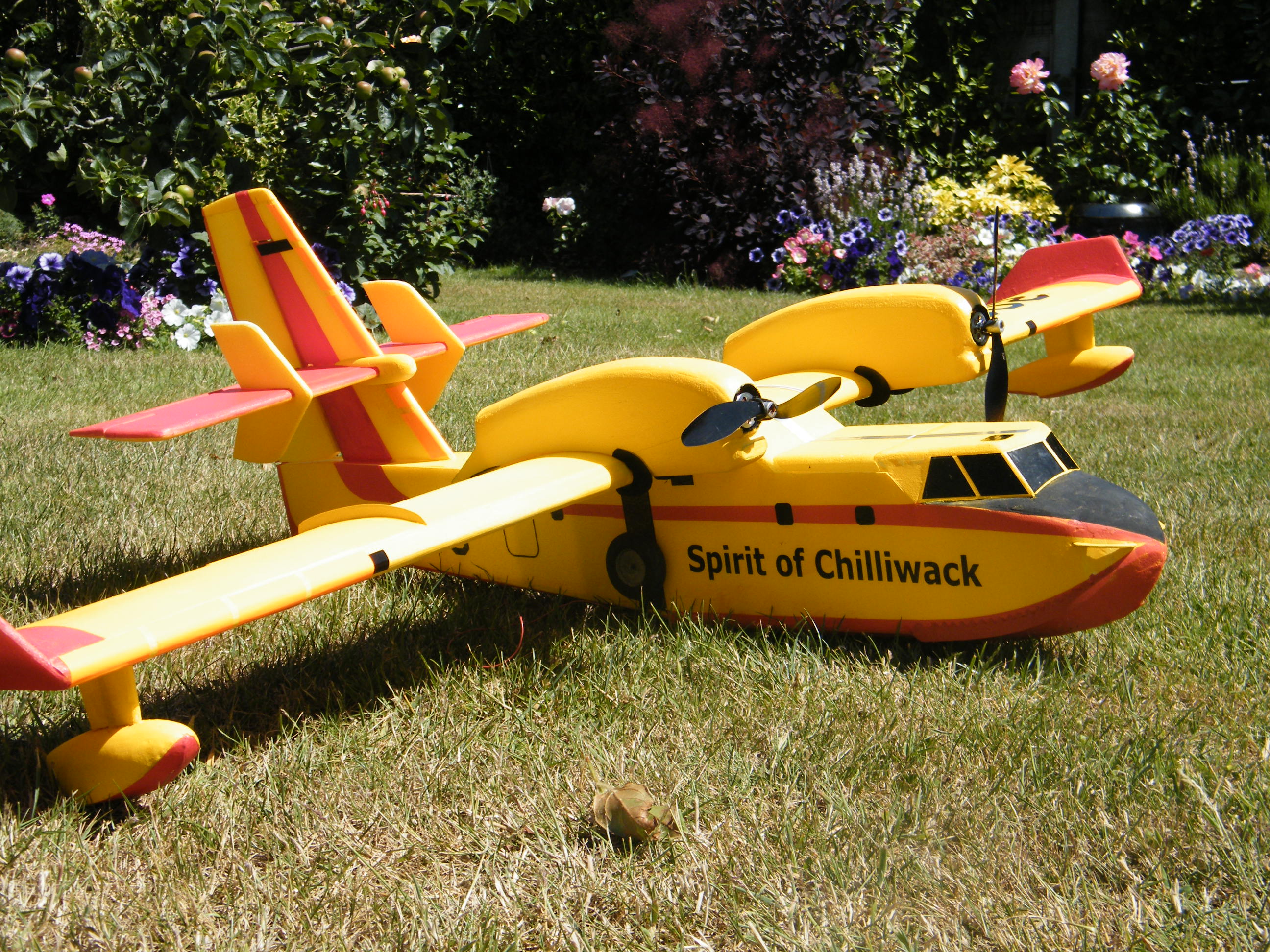
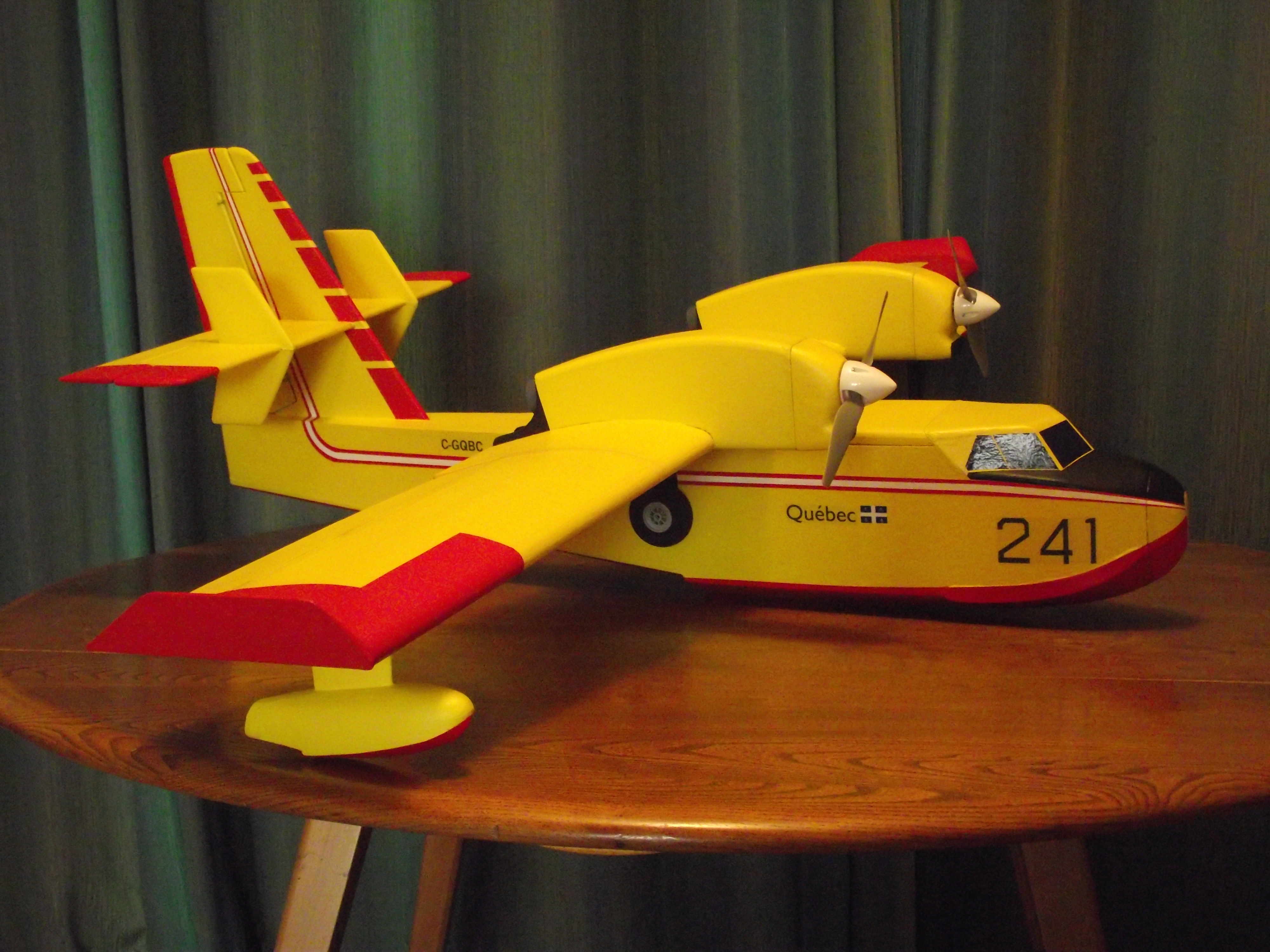
The biggest scale difference from the old plan is the slim line engine nacelles, which are much sleeker than the ones on the plan, and a couple of smaller less obvious points which I will cover as they occur. The new nacelles are as wide as the old ones but have a much lower profile. I’ve drawn the new shape but kept the same method of construction – i will be available as a pdf on my RC Groups free plans thread, as are a number of minor changes to the various laser-cut pieces in the short kit.
My main concerns with “my” parts and “my” plan were three-fold: many of the parts didn’t actually fit: the wing plan couldn’t decide whether to use cap strips or not (so the rib depths were suspect) and the very hard balsa supplied for the fin parts was actually far too hard. Having said that, it was easy enough to cut new parts or modify the ones in the kit and once started most parts went together well enough. The fin parts needed a complete re-cut. For some weird reason they were not what I wanted, even 17 years ago!
I decided to make the tailplane in two parts. The original was fixed and very vulnerable. Some CF and alloy tubes made the task easy enough but the fin needed strengthening for the fittings.
Enough chat. The pictures below are of the build so far. If you have been following the build on the Club Whatsapp you can turn away now!
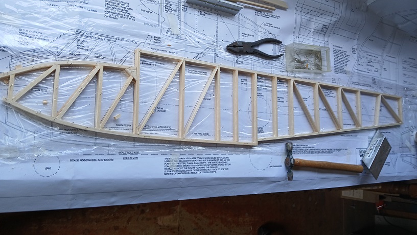
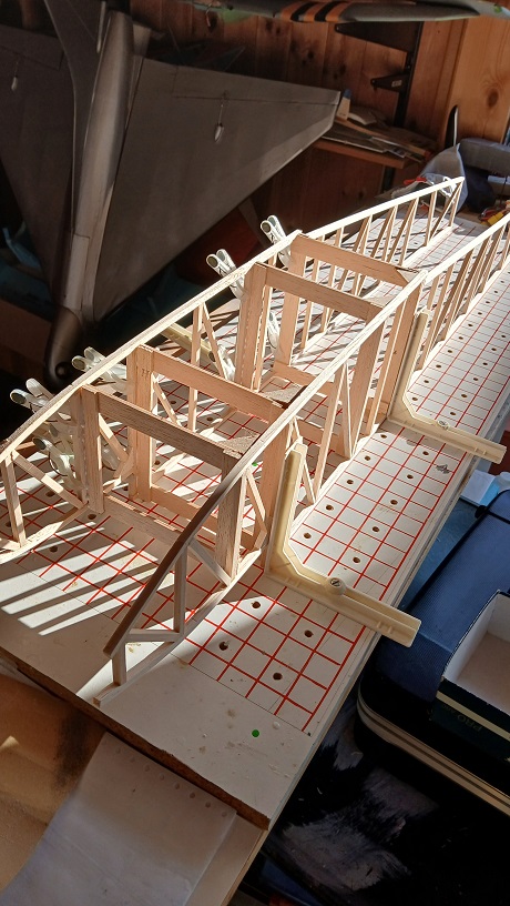
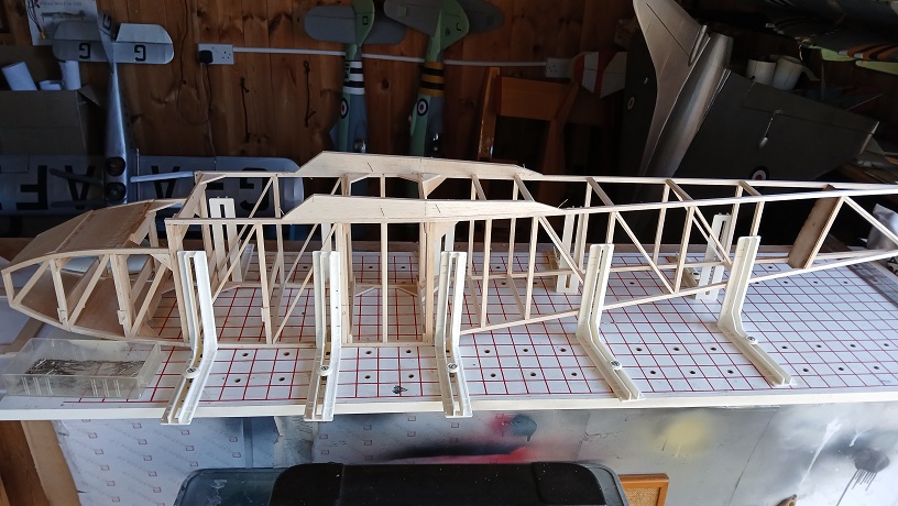
The basic fuselage construction in 6x6 and 6x3mm sticks was pretty much the same, except I lowered the wing seat and reduced the wing incidence to a more sensible level.
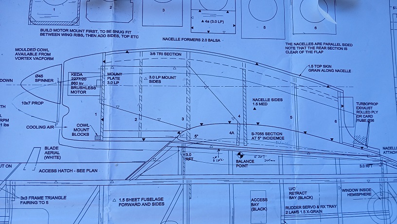
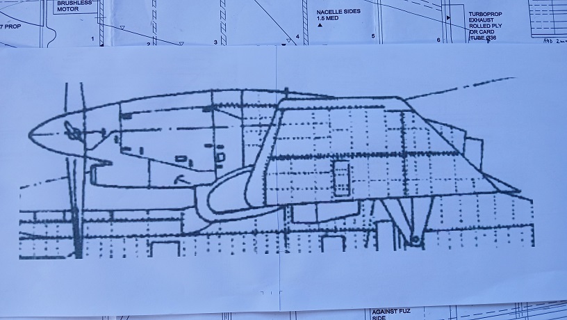
Perhaps you can see the difference in height of my earlier nacelle and the scale version. The drawing is from the Seawings website.
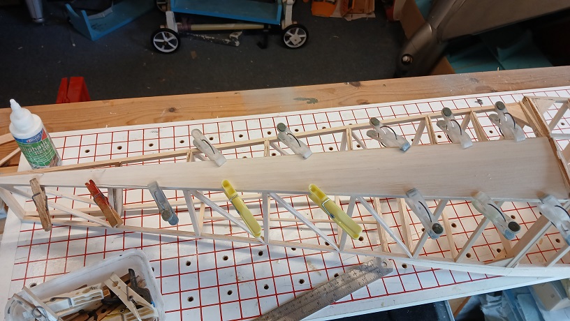
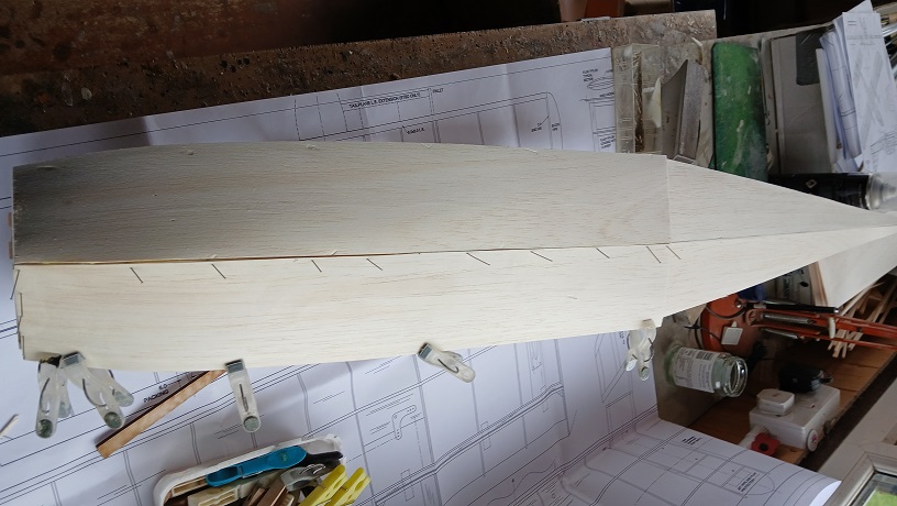
The underhull is a straighforward sheeting job, with 1.5 balsa at the back and 2.5 at the front.
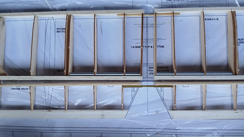
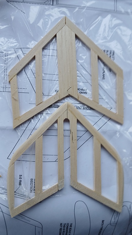
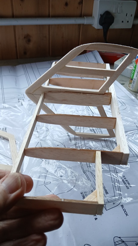
To avoid the inevitable hangar rash from a fixed tailplane,I used a CF rod, alloy tubes and dowel incidence rods. The elevators are joined with square section tubes. The very obvious finlets are from 3mm balsa. On the real thing they are set up at about a degree of left offset, presumably to reduce torque reaction and the load on the pilot during acceleration.
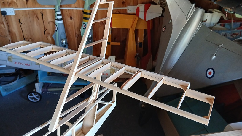
Still got to reinforce the fin sides to cope with the flight loads
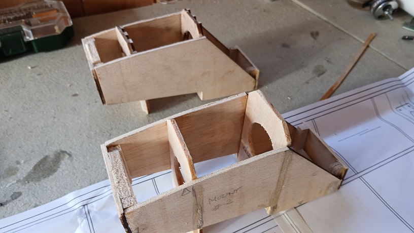
The revised motor mounts for the new slim-line nacelles. They slot in between ribs, main spar and false LE
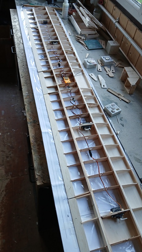
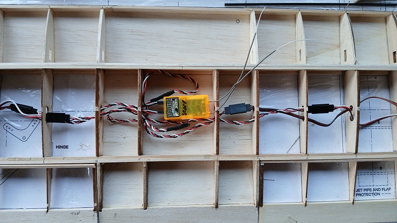
The wing construction was simple enough despite the designer chappie not telling the plan people that he wanted cap strips on all the aft ribs...The wing has all but two of the servo leads, so it’s simpler to put the RX in the centre. It also makes all the testing much easier when the power wires are installed
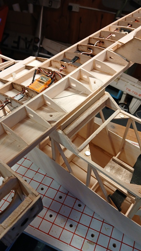
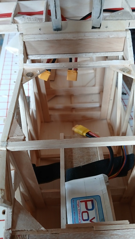
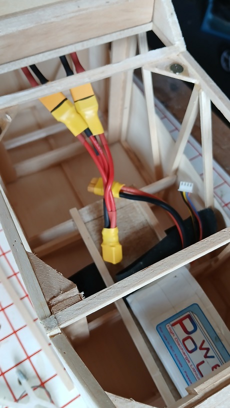
The original wing was bolted down front and rear, but I’ve installed a ply former to take dowels - much easier to rig! The power wires Y-lead into the batttery. I always use Frank’s heat shrink tip for the plugs since seeing him demo it at one of the technique talks a couple of years ago.
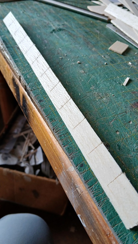
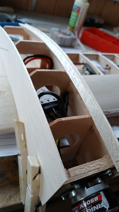
The nacelles ave rounded edges, so I used a very old technique of sawing most of the way though triangular section balsa to allow it to follow the curve of the nacelle top
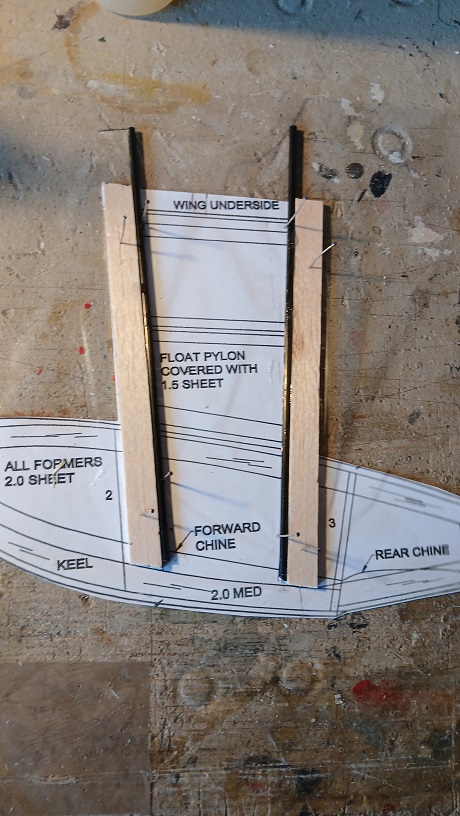
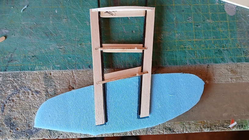
And this is as far as I’ve got. Foam floats are so much easier than balsa frame and planking!
