|
|
|||||||||||||
|
Christchurch and District Model Flying Club |
|
MEAN GREEN CHILLI POWER – Part 1 Tim Calvert
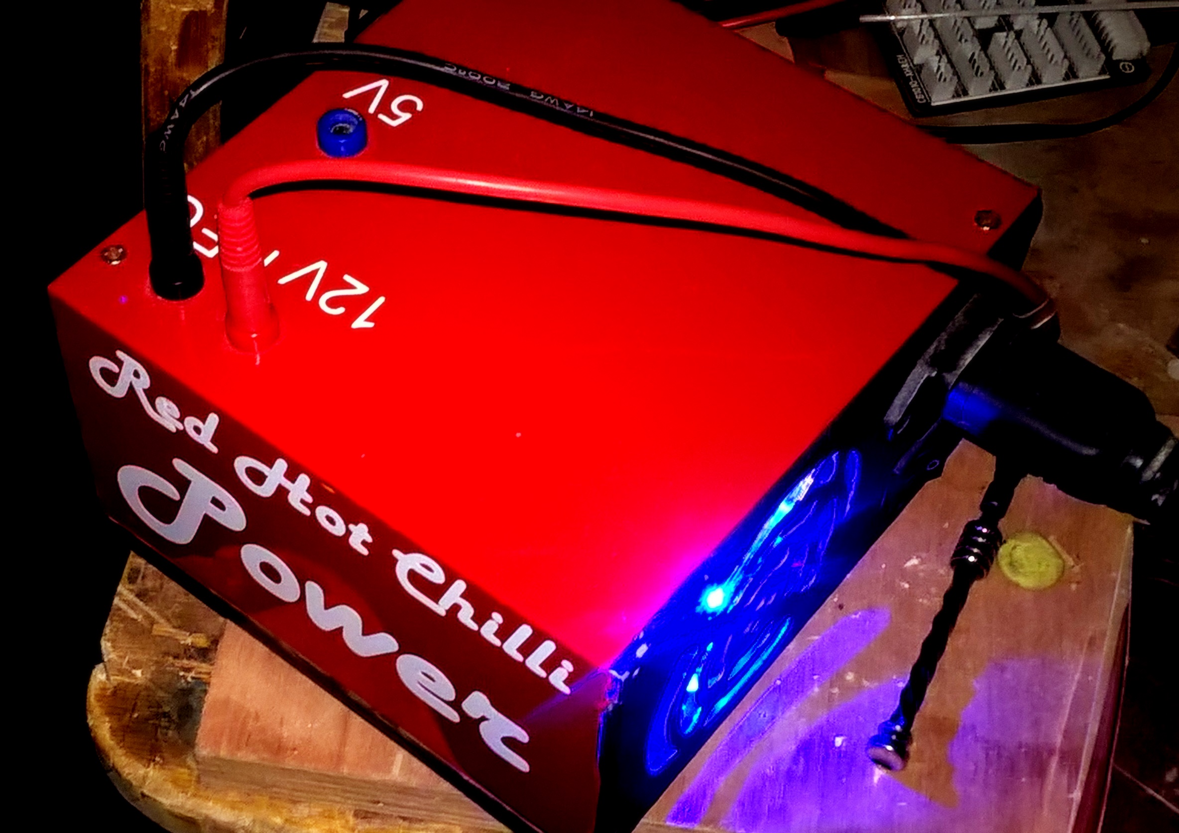
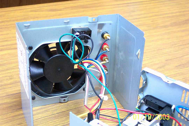
As a follow on from the demonstration at the Club Meeting in September 2016, this and subsequent articles will follow the conversion of the ex computer ATX power unit used in the demonstration and to incorporate some of the ideas discussed in the meeting. The ATX unit is rated at 400w, a useful increase over the 300w Unit used to create my existing Red Hot Chilli Power unit and will provide a comfortable margin to power 2 Lipo Chargers running in parallel. MEAN - because I am a cheapskate, total conversion costs less than a fiver GREEN - Recycling components otherwise heading for the Skip CHILLI POWER – 400w of power capable running 2 12v chargers in parallel The PLAN Features to be included 2 x 12V output – to allow dual LIPO chargers 2 x 5v output USB ports for connecting USB devices such as charger used for some indoor batteries and even my Mobile phone out in the workshop 2 x 5v Servo outputs Change FAN for LED unit. The information below is generic information gleaned from the Internet and covers the general points in converting an ATX (and other Computer Power supplies) for RC use. WIRING COLOUR CODING First you need to understand the colour of the Wiring to understand the colour of the Wiring to identify the 12v, 5V and Neg (ground) outputs This ATX PS board has leads for +5 (RED), -5 (WHITE), +12 (YELLOW), -12 (BLUE) volts, Ground (BLACK) and switch (GREEN). Be warned that some DELL power supplies manufactured between 1996 and 2000 do not follow the industry standard pinout and color codes. Pic showing Fan unit and underside of the fitted 5v and 12 v outputs (4mm Binding Post Sockets)
For R/C applications, the 5 volt output can also serve as a desktop source to drive receivers and servos. (and for USB 5 volt chargers).
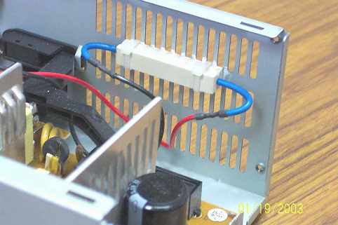
10 w 10 ohm resistor unit in place Power supplies in today's computers are known as SWITCHMODE or Switching Mode power supplies and require a load to continue to operate after being switched on (the term switching mode actually applies to the technique of A/C to D/C conversion and not to the power up action). This load is provided by a 10 watt, 10 ohm wire wound load resistor across the +5 volt supply While many of the newer power supplies will Latch On without a preload, you will find that adding the resistor will (1) increase the measured voltage on the 12 volt rail slightly and (2) help stabilize the voltage level in this rail by minimizing voltage drop when the power supply is loaded with a charger. The sandbar resistor has been zip tied to the case. I will also take a file and remove any stamping flash that may remain around the ventilation slots. Without cooling, the resistor will get very hot and may fail prematurely; with this arrangement, the resistor will remain barely warm to the touch. Wiring coming off an industry standard circuit board will be:
*** Note that the 1996-2000 Dell's did not completely follow this color coding -- check your voltage levels with a meter before wiring *** The yellow, red and black wires will likely be grouped together with a clip. Some of the PS's will have a detachable plug for the fan and some will have the fan permanently attached to the circuit board. If the fan is attached, clip the wires then re-solder and cover with heatshrink tubing -- this gives more working room while modifying the PS. If you are going to use only the +12v and +5v, you may clip the other wires at the circuit board level or leave the unused wires about an inch long, gather common colors together, slip a piece of heatshrink tubing over the bundle and shrink -- it is an easy way to corral and insulate loose ends. For the +5 / +12 volt PS, you will need the following combinations:
Use a single common post (GND -- black) for all voltage sources. Loads are light and we don't require separate grounds for each.
When reassembling the case, be sure to reattach the fan -- some supplies will not function without the fan attached - in any event, you need the cooling. More next edition
|
| [Home] [Chairman's Chatter] [EASA Drones] [Fly Diary] [Wild Thing!] [DeNight Special] [A week away] [Wise Brianman] [Mean Green...] [Tailpiece] |


